


- 3D
- Introducción
- Resumen de funcionalidades.
- Vistas 3D
- Introducción
- Crear una vista 3D
- Propiedades de la vista 3D
- Herramientas de navegación
- Gestión de encuadres
- Salvar y recuperar Vistas 3D
- Pantalla Completa
- Modo de proyección
- Vista estereoscópica
- Insertar vista en el layout.
- Trabajo con capas en 3D
- Introducción
- Añadir capas
- Añadir capas raster
- Añadiendo capas vectoriales
- Propiedades de las capas vectoriales 3D
- Creación de la caché de visualización
- Capas de objetos 3D
- Edición de capas de objetos 3D
- Tabla de contenidos
- El menú de contexto de las capas
- Edición de propiedades
- Cacheado de la leyenda
- Simbologia 3D
- Extrusión
- Etiquetado
- Transparencia
- Propiedades específicas
- Refrescar capa
- Zoom a la capa
- Copiar, cortar y pegar capas
- Trabajando con Tablas
- Herramienta de información
- Herramienta de selección en vista
- Servicios de búsqueda remota
- Animación
3D
Introducción
The purpose of this manual is to instruct the user in the use of the new 3D extension for gvSIG. It is intended here to give an exhaustive and systematic description of the functionalities that the 3D plugging has.
Resumen de funcionalidades.
The functionality of the 3D extension can be subdivided into two groups: on one hand new elements that have been added to the gvSIG user interface and on the other elements that were already present in gvSIG but that have been adapted to function from within the 3D extension in a transparent manner to the user.
- New Elements
New type of document, the 3D view
New type of 3D object layer
- Properties window of the 3D view
- Navigation tools
- Combined navigation (includes the three following controls)
- Control of displacement or panning
- Control of altitude (zoom)
- Control of azimuth and inclination (rotation around a central point)
- Orientation mode (to the north or free)
- Complete zoom
- Menu options:
- Tool of interactive control of the transparency
- Option to refresh layer (In the contextual menu of the layers)
- Properties of the 3D layers.
- Visualization tools:
- Visualization settings tool (stereo modes, display type).
- Projection mode (perspective, ortographic)
- Fullscreen mode.
- Wireframe mode.
3D Symbology, 3D objects in points
Extrusion legend
The elements shown next are kept the same, although in many cases there have been small modifications done to their codes so they can work in the 2D view as well as in the 3D view (see architecture section).
- Re-used elements
Project manager
Table of Content (TOC) of the view
Tool to add layers
Menu option and properties window of the layers, including symbology
Tool and window for setting management
Information tool
Selection tool
Tool and windows to search for geodata in catalogue services
Tools and windows to search for toponyms in nomenclator services
- Menu options of the application
Project file (new, open, save)
View (console, project manager)
- Layer
- Erase selection
- View attribute table
Window (same options are kept)
- View
Add layer
- Navigation (in addition to the tools described above):
- Zoom to selection
- Bookmark manager
View (3D) properties
- Contextual menu of the layers:
- Rename
- Change colour (for vector layers)
- Properties
- Raster and remote services properties (only read)
- Zoom to layer
- Delete layer
- Cut / copy / paste layer
Vistas 3D
Introducción
The 3D extension for gvSIG adds a new type of document called 3D View. In many ways, this new type of document behaves as the normal views.
Crear una vista 3D
Once the 3D extension is installed in the gvSIG Project Manager, two new types of documents will show up, 3D View and Animation. All the options of the Project Manager can be applied to these types of documents: create a document, open, rename, delete and show properties. To create a new view, simply click on the button “New”.
In this section the “3D View” document will be explained
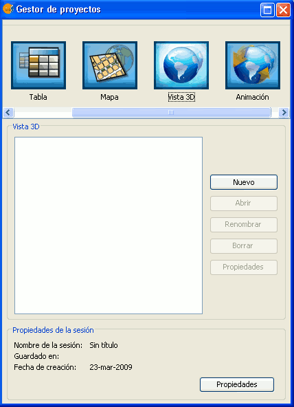
Project Manager
It is possible to create multiple 3D views and to work simultaneously with the other types of gvSIG documents: 2D views, tables and maps.
Propiedades de la vista 3D
The 3D view is different from the normal 2D in that some of the properties must be initially specified and cannot be change later on. Because of that, once a 3D view is open for the first time (by clicking on the “Open” button of the Project Manager or double-clicking on the view’s name) the properties window of the 3D view will pop-up open.
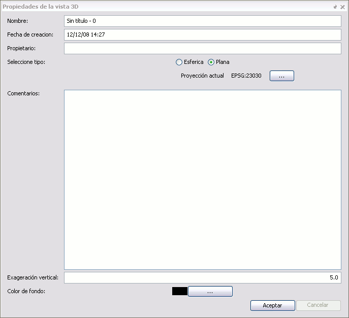
Properties of a 3D view
Spherical and Planar Views
In the properties window there is a property, proper to the 3D view that specifies if the view is of the planar or spherical type. This property is defined at the moment of opening the view for the first time and it cannot be change posteriorly. In a spherical view the data is visualised over a planetary ellipsoid, whereas in the planar view the geographical coordinates are visualised over the XY plane and the elevation along the Z axis.
In the planar 3D view it is possible to define the coordinate system. If we click in the button labelled as “Current Projection”, it will be possible to select the projection we would like for the planar 3D view. On the other hand if we select the spherical or planetary view, the view will have by default the coordinate system WGS84 (projection 4326).
Vertical Exaggeration
Another of the properties specific to the 3D view is the vertical exaggeration factor. The elevation values will be multiplied by that factor at the moment of performing the visualisation, so that the elevation values stand out more or less. This value can be changed any time.
Background colour
In the case of the 3D view the background colour is applied to the background space where the planetary globe or planar view is visualised. This value can be changed any time.
Herramientas de navegación
In the gvSIG 3D plugging offers simple navigation tools. When the 3D view is active, the navigation tools can be found in the application tool bar or in the View menu.
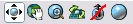
Navigation Controls
These tools function the same way in the spheric and planar views.
Displacement / panning

This tools allows the user to displace the anchor point over the terrain surface or in other words, to move the surface in the 3D view.
Altitude control / zoom

Once this tools is active, the user could change the altitude with respect to the anchor point in the surface, by left-clicking and dragging the mouse up and down. This effect is more or less similar to the zoom in the 2D view.
Azimuth and inclination control (tilt and rotate)

When this tool is activated, the user can pivot around the anchor point over the surface. The horizontal displacements with the mouse control the azimuth (if the North-up orientation mode is not active) and the vertical displacements control the inclination.
Combined navigation

When this tool is selected, which is in fact the default active navigation tool, the three previous actions can be combined as follows:
- Left button of the mouse controls the displacement / panning.
- Middle button controls the azimuth and inclination.
- Right button controls altitude / zoom.
North-up orientation mode

When this mode is active (the red line disappears in the icon) the view is always oriented with the geographic North at the top of the view. This allows, for example to displace or pan without loosing the orientation.
Full Extent

When this tools is activated, the view will show the entire geographic space or globe.
Gestión de encuadres
The Bookmark Manager Tool  can be found in the tool bar and also in the View menu. Once this tool is activated it will open the Bookmark which is identical to the open used in the normal (2D) views.
By using this manager, actual positions within the 3D view can be saved with names and can be retrieved to be used within the same 3D view or others views defined within the project. These bookmarks however, are kept separate from those saved from within the 2D views.
Salvar y recuperar Vistas 3D
To save the content of the 3D views simply use the menu option File/Save Project or the corresponding tool in the toolbar. When the project is saved in a .gvp file all the properties corresponding to 3D view are stored in that project file. In the project it is also saved the bookmarks list defined for the 3D view which could be used in posterior sessions.
To retrieve a project where there are saved 3D views, it is only necessary to use the File/Open Project menu or the corresponding tool. The 3D views will be restored to the position in which they were saved, including the layers and extent.
Pantalla Completa
The tool to set full  screen can be found in the toolbar when a 3D view is active.
This tool is used to set the contents of a specific 3D view to full screen. It has been implemented inside the 3D extension so it can be used for presentations and shows. This tool is the perfect complement to the stereo one since by combining both they can be used to look at 3D views in virtual reality immersive systems.
Tool Options:
Synchronize cameras: If this option is selected the cameras from the gvSIG views and from the full screen are synchronized. This is option is used when there is an animation running over the 3D view, this way the full screen view moves with the animation.
Screen selection: By activating this option the user could select in which screen to visualize the full screen. This is useful when the user has more than one monitor.
- Window Mode: It is used to show the view in window view only. This will show only the interior of the 3D view (without the TOC or the locator).
- Origin position: It shows the position of the upper left corner of the window.
- Resolution: It shows the width and height of the window.
Enable Philips WOW display stereo mode: Configures the fullscreen mode for the visualization on Philips autostereoscopic diplays.
Note: The full screen mode duplicates the 3D view that gvSIG is using. This causes a drop in the system performance if there is no sufficient memory and graphics hardware available.
Modo de proyección
The projection mode tool  can be found in the toolbar when a 3D view is active.
This tool is used to change the way in which the 3D graphics are projected (it has nothing to do with the view or layer projections). In other words, the 3D views can be projected basically in two ways: orthographic or perspective. This tool changes between these two types of projections.
Note: When the orthographic mode is active it is not possible to zoom in the view. There are only the options of panning or rotating.
Vista estereoscópica
The stereo tool  can be found in the toolbar when the 3D view is active.
This tool is used to activate or deactivate the stereo in the view. It is made up by the following options:
- Stereo visualisation: Indicates the stereo mode to create the stereo. Stereo types:
- None.
- Anaglyph.
- Horizontal interlacing.
- Vertical interlacing.
- Horizontal Split.
- Left eye.
- Right eye.
- Quad buffer.
Interocular Distance: Distance between the eyes. Usually between 0,06 y 0,055.
- Screen type: Screen over which the stereo content will be visualised. Options:
- Monitor.
- Head-mounted display.
- Powerwall.
- Virtual reality centre.
Distance to screen: Distance from observer to the screen.
Fusion distance increment. Modifies the fusion distance used to in the stereo calculation.
Insertar vista en el layout.
The steps to follow in order to insert a view in the layout are the following (assuming one or several 3D views):
- Create a type of map document.
- Click in the insert 3D view button
 in the layout.
 - Move the 3D view to adjust as desire.
Note: Unlike the 2D view of gvSIG, in order to adjust the 3D view in the map it is necessary to move the view itself. If the adjustment is done on the inserted view in the map, there will be no effect over the view.
Trabajo con capas en 3D
Introducción
The layers of information in the 3D views are exactly the same as in the normal views, thus the way to work with them is the same.
In the 3D extension a new layer type has been added. They are called 3D objects. These layers contain objects tridimensional modelled. Their functioning will be explained later on.
Añadir capas
The same tool “Add Layer” used in the normal views to add layers is used in the 3D views, using the same data source types. The window to select the layers to be added is exactly the same:
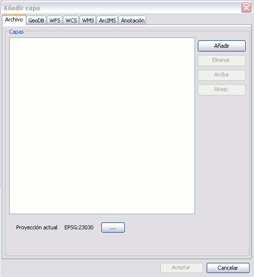
Adding layer window
Añadir capas raster
The data sources providing information of raster type are raster files and the WMS, WCS and ArcIMS Map services. The 3D views allow representing the raster data in two ways: as images (flat over the terrain surface) and as elevation (defining the terrain relief).
The 3D extension offers to the user the option to represent a raster as elevation in the following cases:
- For raster files, when they only have one band (normal situation with digital terrain models - DTM’s).
- For WMS services, when the TIFF or geoTIFF formats are selected. In the case the raster is to be used as elevation, it would be necessary to choose a style allowing for those values, usually indicated as "integer", "unsigned int", or 16 (or more) bits per pixel.
- For WCS services, when the GEOTIFF_INT16 is selected and there are no parameters (bands) selected.
In the case that is possible to use the raster as elevation the following dialog will appear:
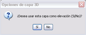
Loading option dialog of layer as elevation layer.
Only one elevation layer will accepted in each 3D view. If the user tries to add additional layers to the view the following message will appear:
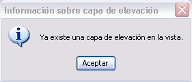
Control of additional elevation layers dialog.
At the moment gvSIG is able to reproject rasters, therefore there should not be any problem using layers with different reference systems to the view.
Añadiendo capas vectoriales
The data sources that can provide information of vector type are the vector files (SHP, DWG...), the vector databases and the WFS y ArcIMS Feature services.
The 3D views allow representing vector data in two ways: rasterised, as images glued over the terrain surface, and as three dimensional objects. The 3D extension offers the user the two options for all the mentioned data sources, although the results obtained with the ArcIMS Feature Service is not adequate for representation as 3D objects given how it draws this type of layer.
When the user adds a vector layer to the view the following dialog will show:
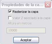
Vector layer options.
When the rasterisation option is deactivated to represent the vector data as objects in 3D, the elevation values (Z component) given by the geometry of the data can be used. If this option is selected and the geometry does not contain Z values, it will default to zero. This can complicate the visualisation in 3D since the terrain surface will mask the data.
Because of that, if the vector data does not contain elevation it would be better if the user assigns an elevation value in meters using the entry field in the lower part of the dialog.
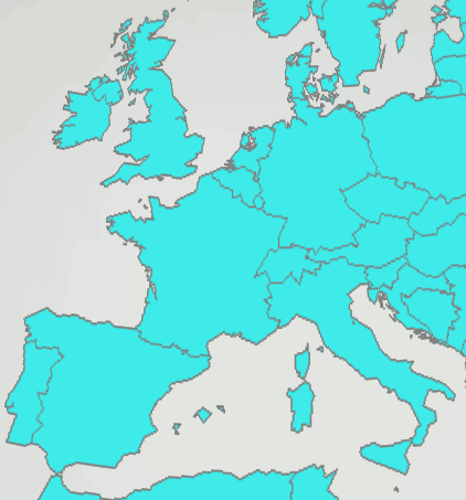
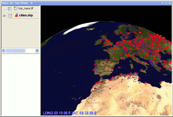
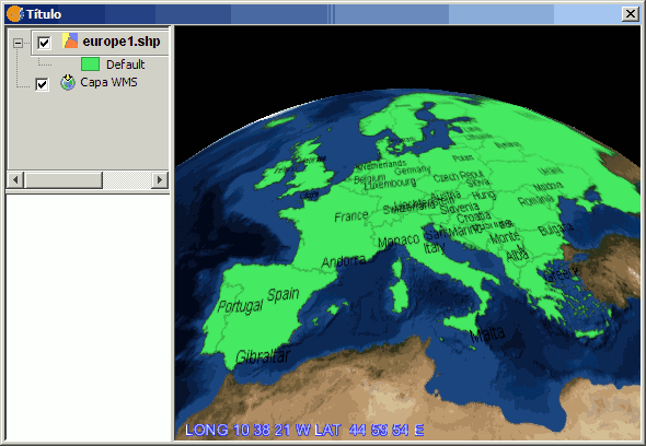
Example: Capture of layer with rasterised polygons in Europe.
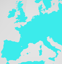
Example: Capture of layer with un-rasterised polygons in Europe.
Propiedades de las capas vectoriales 3D
As it was shown in the previous section, it is necessary to indicate in which way the vector layers will be represented in the 3D view. It is possible to change the type of representation by using the 3D properties of a layer.
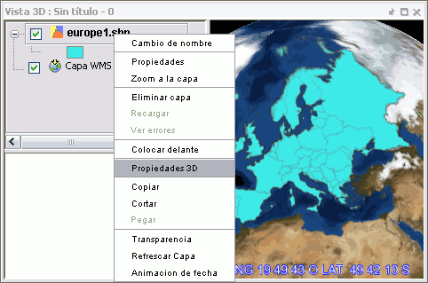
If we go to the TOC and right-click over the vector layer, a context menu will appear. We will select “Propiedades 3D” and the following dialog will show up:
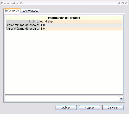
If we go to "Opciones" in the “Capa vectorial” tab, we could modify the way to represent the 3D layer.
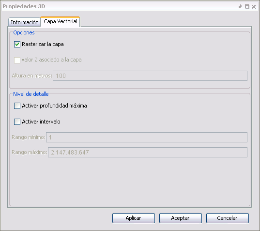
In the same windows we could see there is another section “Nivel de detalle” and there are several other related options:
- Activar profundidad máxima: This option calculates the maximum depth to which the layer is valid and does not continue subdividing.
- Activar intervalo: This option indicates over which subdivision interval the layer is visible.
Creación de la caché de visualización
Once having added layers, either as images or elevation layers it should be noted that data takes some time to become visible at their maximum resolution. This happens because the 3D extension creates a multi-resolution representation of the layer in the local hard drive which is used for quick visualisation of the data at different scales. This visualisation cache is actually stored in the local folder gvSIG\.data\cache\Earth within the user’s root directory.
The first time data is visualised or when the scale or the view is changed, the cache generation process is executed automatically. The speed of the cache creation will depend on the speed to access the source (it will be much slower for remote services) and the complexity of the data (e.g., vector quantity). Once the cache is created, panning within the same area will render fast and interactive visualisation. However, if the properties of the layer are changed and they affect the existing cache, this will be recreated automatically.
There is a way to force a cache to be invalid (See the “Refresh Layer” section).
Capas de objetos 3D
Upload layers of 3D objects
The layers of 3D objects are loaded in the same way that layers are loaded for a vector or raster file.
In the dialog of add layer from file, click on the add button and under "Select file type" select GvSIG OSG Driver
The formats of 3D object layers that GvSIG can load are files of type .osg and .Ive.
To learn how to generate those formats refer to the section Create layers of 3D objects and Save layers of 3D objects.
Create layers of 3D objects
The tool to create 3D object layer  can be found on the toolbar when a 3D view is active.
When you click on the create 3D layer button, a new layer of vector type is created immediately and a message appears indicating that the layer has been automatically set to editing mode.
Save layers of 3D objects
The tool to save layers with 3D objects  can be found in the toolbar when you select a 3D objects layer in a 3D view and is also it activates the editing mode of that layer.
If we click on it you will get the following dialog box, where we can select the path and file format (*.osg or *.ive) in which we want to save the layer.
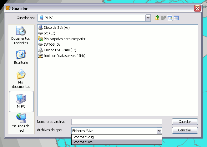
Note: The file format *.osg is an ASCII type while the file format *.ive is a binary type.
Edición de capas de objetos 3D
Enabling/disabling editing of 3D object layers
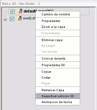
To enable/disable editing of 3D object layers simply click on the selected layer and right-click on it. In the context menu select Enable 3D editing, if you want to activate the 3D edition or Off 3D editing, if you want to disable the 3D edition.
Insert 3D objects
The tool to insert 3D objects  can be found in the toolbar when you select a 3D objects layer from a 3D view and also the active layer is in editing mode.
If you click on it you will see the following dialog box:
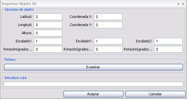
Where each item means:
- Object options
- Latitude, longitude and height: Position of the 3D object is defined by its latitude, longitude and height. Contingent to the projection (spherical or planar) of the object view, they need to be set to meters or degrees.
- X and Y coordinates: These are the X and Y coordinates of the screen.
- Scale X, Y and Z: Scale that we want to give the object initially. You can change it posteriorly, look at manipulation of 3D objects
- Rotation X, Y and Z: rotation that we want to give the object initially. You can change it posteriorly, look at manipulation of 3D objects
File: If you click on the browse button, you can choose the 3D object you want to load.
Enter path: You can enter the path to the file containing the 3D object.
Insertion using the mouse: Once you open a dialog to insert 3D objects, if you click on the 3D view the fields of latitude, longitude and height are automatically filled in order to visually place the 3D objects.
- Note:* The file formats supported are *.ive, *.osg, *.3ds, * obj. (Future versions will include more).
Manipulating 3D Objects
To manipulate 3D objects is necessary to enable the editing of 3D layers and have selected the layer to be manipulated.
- Selecting a 3D object: Clicking the left mouse button on the item you want to select.
- Unselecting a 3D object: Clicking the left mouse button outside the 3D object.
- Ungroup 3D object: With the object selected click on the icon from the toolbar or press the letter G.
- Group 3D object: With the object selected click on the icon from the toolbar or press the letter U.
Types of manipulators:
- Tab Box Dragger: Manipulator where a wrapping box appears around the object, and through which the 3D object can move in any direction. You can also use it to scale the 3D object

Icon on the toolbar.
- Track Ball Dragger: Manipulator where there is a sphere enclosing the object, and by which you can rotate the 3D object in any of its axes.

Icon on the toolbar.
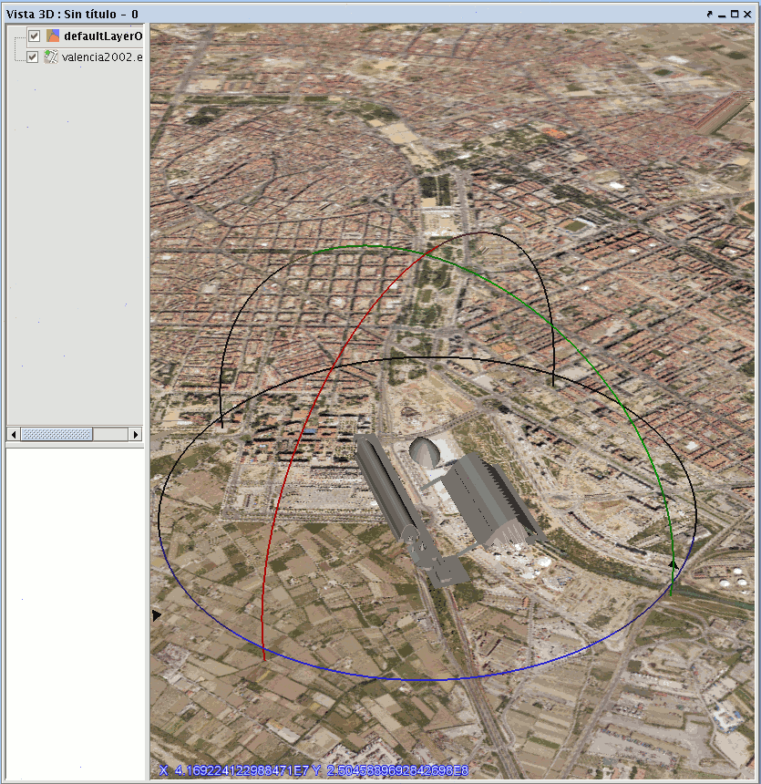
Tabla de contenidos
The Table of Contents (TOC for short) included in the 3D view behaves exactly like the TOC of the 2D view, showing the layers added to the view and legend.
As in the 2D view, you can use the TOC to easily change layer visibility. In the case of the elevation layer, if this is made not visible the elevation will disappear from view, leaving surface with no relief.
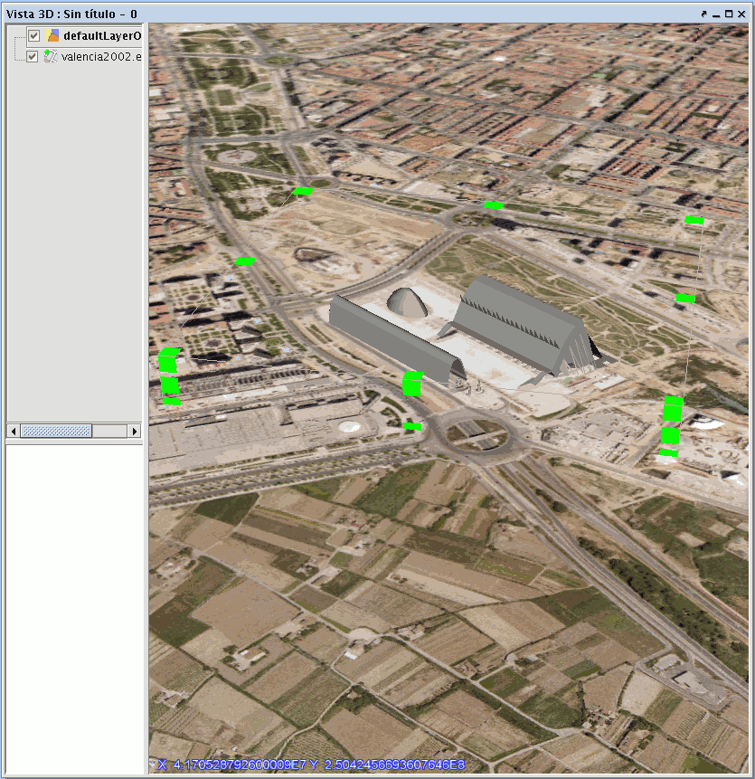
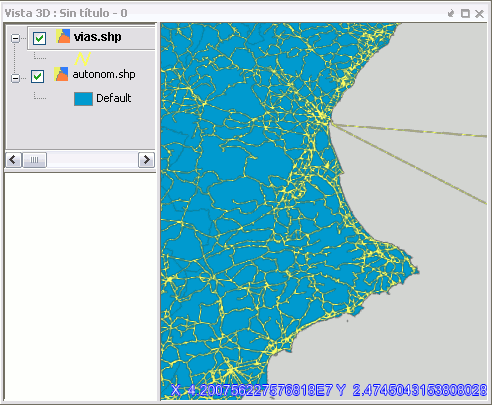
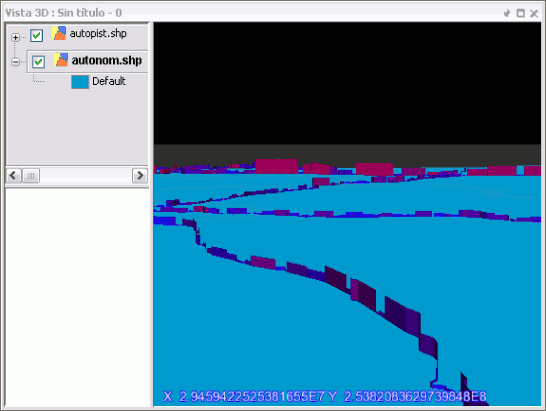
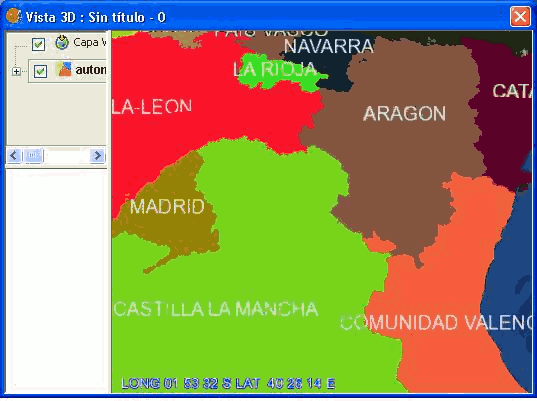
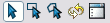
Another feature of the TOC is to control the display order of the layers (which are visible over the others). That is achieved by dragging the layers up or down. In the 3D view this order applies only to the vector or raster image layers, but does not affect the layers of 3D objects or elevation layer. The following example shows how the order affects two vector raster layers but has no effect on the elevation layer.
TOC and corresponding 3D view
El menú de contexto de las capas
In the 3D view TOC layers have a context menu practically the same as the normal view, with some additional tools. We will discuss the most relevant options.
Edición de propiedades
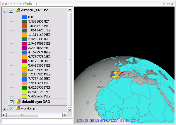
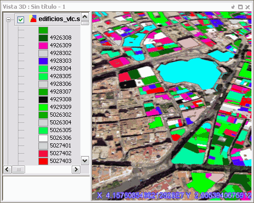
Using the context menu you can change the name of the layer, color (in the case of a vector layer with single symbol) and edit its properties window. In the case of changing certain properties, like the legend, the display cache is re-calculated layer, usually automatically. The figure shows the appearance of a polygon layer used in previous examples, after changing his legend to unique values.
The properties of symbols are applied to layers represented as images in the same way as would apply in a 2D view (eg the thickness and style of the lines).
Moreover, in the case of vector data represented as 3D objects, the application of the symbology is limited to the size of dots and lines, and color of symbols.
Note: A new type of legend called extrusion and a new kind of symbol for 3D points have been created. Look in the Extrusion and 3D Symbology sections.
Cacheado de la leyenda
In the cache for rasterized vector layers, the legend is also saved in .xml. When the same vector data source is added back as a layer, this legend is assigned by default, allowing for the reuse of the cached images. If the legend changes (see above), the cache is rebuilt and the new .xml file is saved.
Simbologia 3D
Using the power of the new symbology framework. The 3D plugin has added the possibility of inserting a new symbology for points. Specifically, we can generate a 3D Object type symbol and insert it as a symbol in a 3D layer-type vector point.
To do this open the "Symbol Properties Editor (see the manual gvSIG version 1.9-Alpha or later). In the panel for "Properties" we will deploy the list and select where it says Object 3D symbol and a panel will appear as shown below:
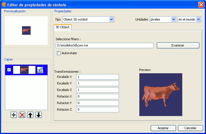
And where the boxes mean:
- Select files: You must indicate the file containing the 3D geometry.
- Autorotate: If selected, the model is always facing the camera.
- Transformations:
- Scale X, Y and Z: Scale to be applied to the model.
- Rotate X, Y and Z: Indicates the rotation to be applied to the model.
- Preview: Shows a preview of the 3D object. By default a sample model will show.
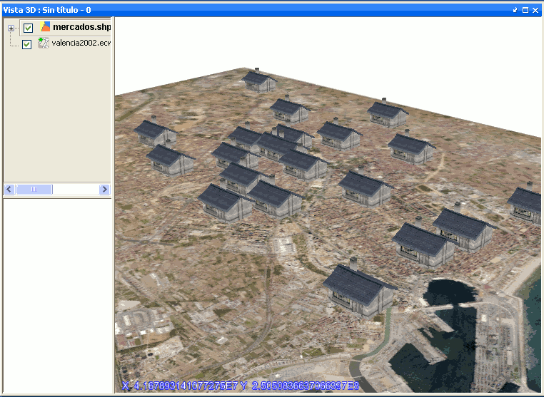
Then add the new model and delete the one given by default and it would show as follows:
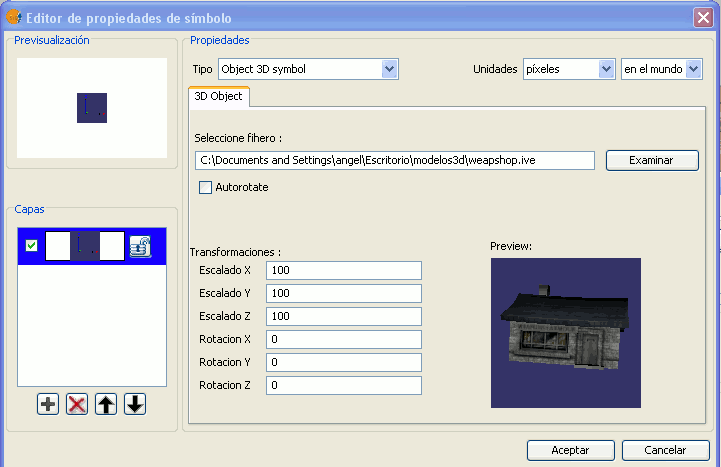
And the result would be.
Extrusión
Extrusion is a new kind of legend that has been created in the 3D plugin. This legend is used to extrude any primitive type (points, lines and polygons) that contains a vector layer in function of a given multiplication value.
A more technical definition of extrusion is:
Generating an object of dimension n+1 by the extension of a object dimension along a defined range in an additional dimension.
To use this new type of legend we have chosen to display as 3D vectors the layer that has been inserted in the 3D view.
Open the legend window and select where it says Extrusion. This window looks much like the legend of unique values. The following screen appears.
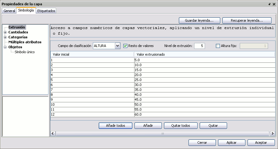
Choose the field on which you want to extrude and the extrusion level you want to apply. Click on the button to add all and accept.
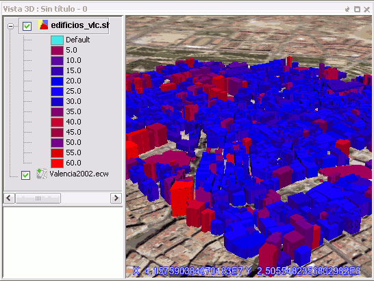
Extruding polygons.
Extruding lines.
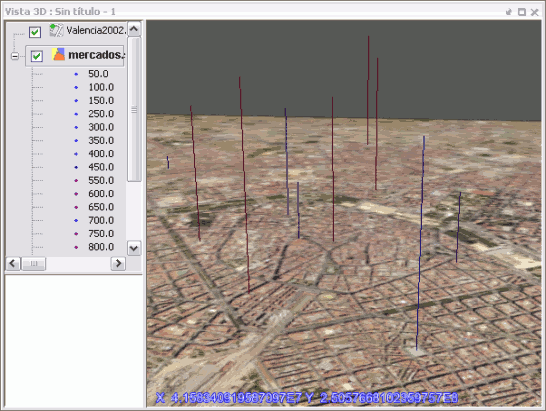
Extruding points.
Etiquetado
Labeling should be consistent whether the vector layer is rasterized or not. When the layer is rasterized, the labels are too. Its size and color is given by the tagging options, like in the 2D view.
On the other hand, when the vector layer is not rasterized, the labels will appear as floating text with the corresponding 3D objects for the data. Their size and color is again given by the tagging options.
Note: Only basic labeling is available in the 3D plugin.
Transparencia
In the context menu of the layers there is an option to change the transparency of an image layer (or rasterised vectors) interactively. This option can be activated from the toolbar and also from the Layer menu.

Icon on the toolbar.
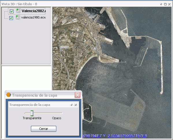
Example of extension of transparency and results.
When the tool is activated, a dialog appears with a scroll bar that lets you change the layer transparency interactively. It must be said that the interactive transparency tool has its impact over the transparency display of raster layers.
Propiedades específicas
Raster type layers and layers of remote services have specific properties that are active in the context menu. In the 3D view these menu options can be used to open the same windows of properties displayed in the layers of normal view.
Refrescar capa
From the context menu of the layer the display cache can be manually refreshed. This may be necessary for:
- Reflect changes that have occurred in the code (for example, if it has been edited)
- Regenerate a cache that somehow got corrupted
- In rasterized vector layers that are loaded from a project file, to generate the visualization cache with the legend stored in the project rather than with the legend cached (which may have changed since the project was saved)
- Force a visual refresh of the layer that does not happen automatically.
Zoom a la capa
This command works the same as in the normal view. The 3D view will change to show the full extent of the layer. In the spherical view, for very extensive layers it will display the full planetary globe.
Copiar, cortar y pegar capas
With the context menu sections of a 3D view can be cut or copy and paste into another normal view or 3D view. Conversely, sections can also be cut or copy from a normal view to be pasted in the 3D view.
When a layer is pasted from a 2D to 3D, the user will be able to choose the same options (elevation or image, rasterization of vectors) that if the layer were added directly from the data source.
Trabajando con Tablas
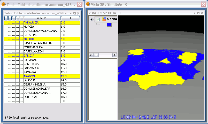
As in the 2D views, the tool 'View Table of Attributes' is available for vector layers on the toolbar and in the Layer menu. When using this tool it will show the attribute table of the active layer and will be possible to perform all the tasks, as sort fields, etc..
Records can be selected in the table manually, apply filters, etc.. The tool 'Zoom to Selected' can be used as in 2D to quickly find the records selected in the view. Also the tool 'Delete Selection' works as in normal view.
Herramienta de información
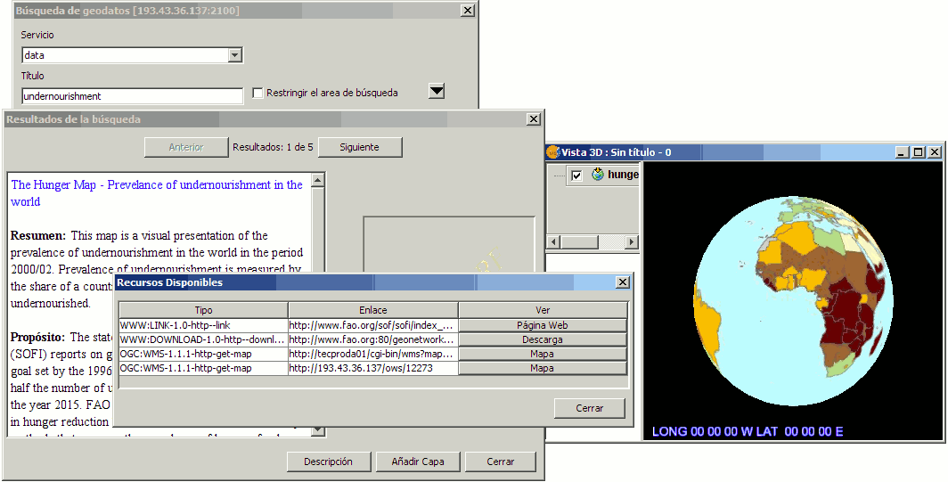
Like many of the tools available to the 2D, the information tool has been adapted to be used in the 3D plugin and it works just like in the version for 2D views. To access from the toolbar press the button:

Information button.
or from the bar menu "View / Search / Information.
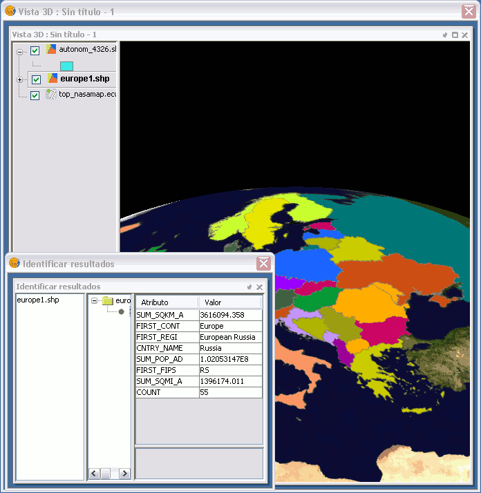
To obtain information about each of the elements of the map the "Information Tool" is used.
When you click on any element with this tool, gvSIG shows, in a dialog box, the attributes of that element. For that to function the layer in which the feature you want to identify has to be activated in the TOC
Herramienta de selección en vista
The selection tool in view has been adapted to be used in the 3D view. It works for raster layers as well as for those that are not.
Selection options.
Selected area in yellow.
Servicios de búsqueda remota
Introducción
The search tools for the geodata remote catalogue and search for place names have been activated and adapted to operate in the 3D view.
Búsqueda en catálogo de geodatos
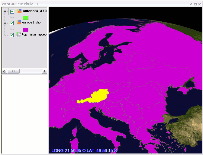
This tool appears when the 3D view is activated. It works the same way as in the 2D view, allowing search by keyword, displaying a panel with the results and allowing the user add the layer if it is defined in the catalogue. The following figure summarizes the steps taken to add a remote WMS layer from the list of FAO.
Similarly you can add layers WCS and WFS, to which the coordinate system of the layer will be assigned, as long it is supported by the service. Note that on adding a layer WFS, the user will be prompted whether or not to rasterize the layer, as occurs when adding any vector layer.
Added improvement in the 3D plugin is that when you press the button to add a WMS service as a layer from catalogue search, it will open the properties window of the remote service WMS, which will allow you to select properties such as style, format and reference coordinate system. This last step is important so that the layer will display properly in 3D.
Búsqueda de topónimos
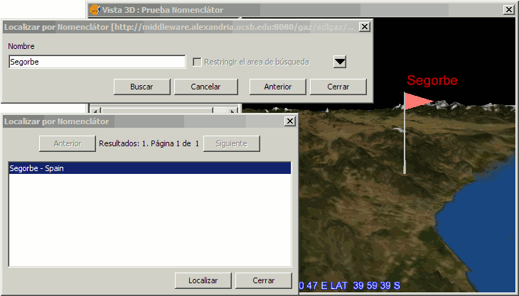
The search tool for placenames also appears when the 3D view is activated and works similarly as in the normal view. In the three-dimensional case, as the user press the button 'Locate' a flag is added to the view that indicates the coordinates of the name searched, along with a textbox displaying the name.
Animación
Introducción
En esta sección se realiza una descripción de las funcionalidades añadidas para la creación de animaciones para vistas 2D como para vistas 3D.Resumen de funcionalidades
Partiendo de la creación de un nuevo documento, llamado documento de animación, que se añade al gestor de documentos al instalar la extensión, se puede acceder a un conjunto de herramientas para la creación de animaciones.
- Elementos nuevos
- Nuevo tipo de documento, documento de animación.
- Herramientas de captura de vista
- Herramienta de animación de capas
- Controles de reproducción
- Animaciones en vistas 2D
- Animaciones en vistas 3D
Documento de animación
Introducción
La extensión de 3D añade un nuevo tipo de documento llamado Animación, a través de él se accederá a la opciones de creación de animaciones tanto en vistas 2D como en 3D.
Crear un documento de animación
En el Gestor de Proyectos de gvSIG puede apreciarse la existencia de un nuevo tipo de documento llamado Animación. Todas las opciones del Gestor del Proyectos pueden aplicarse a este tipo de documento: crear un documento nuevo, abrirlo, renombrarlo, borrarlo y mostrar sus propiedades. Para crear un nuevo documento de animación se debe de pulsar la opción “Nuevo”.
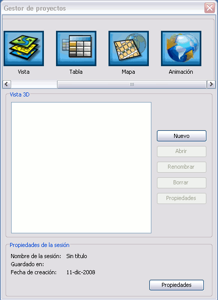
Gestor de proyectos.
Abrir un documento de animación
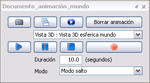
Para abrir el documento de animación, haga doble clic sobre el nombre del documento, o pulse sobre el boton "Abrir" y se mostrarán las siguientes opciones para la creación de animaciones:
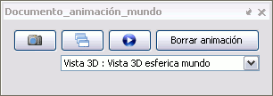
Herramientas iniciales para la creación de una animación.
Herramientas de captura de vistas
A continuación se enumeran el conjunto de controles de un documento de animación relacionadas con la captura de encuadres en una vista.
- Captura de encuadres (fotograma clave):

Botón de captura de encuadres.
Mediante el pulsado de este botón se produce la captura de la posición concreta en la vista (x,y,z). Para la realización de una animación de movimiento, se tomarán las muestras (posiciones en este caso) que sean necesarias, cuanto mas elaborada sea una animación (medida por el número de muestras escogidas y distancia entre ellas), el movimiento será más preciso y suave. La vista se moverá entre dos encuadres consecutivos.
- Selector de vista para la captura de encuadres:
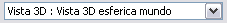
Vistas activas.
El selector de vistas incluye todas las vistas ya sean 2D como 3D abiertas en un momento dado, cualquiera de las cuales una vez seleccionada será la vista a la que se le aplicará una animación concreta (ya sea tomando fotogramas clave o aplicándole transparencia).
El selector de vista se irá actualizando con el conjunto de vistas abiertas. Una vista abierta es considerada como una vista lista para poder ser animada. Al seleccionar una vista cualquiera la vista se actualiza en el selector.
Una vista asociada a un documento de animación no puede ser asociada a otro, si no es liberada antes mediante la opción Borrar animación.
- Borrar animación:
Botón de borrado.
Borra la animación de movimiento relacionada con un documento de animación concreto, liberando las vistas para poder ser usadas en otras animaciones.(NOTA: borra el conjunto de animaciones totales contenidas en el documento de animación).
Herramientas de captura de capas
A continuación se enumeran el conjunto de controles de un documento de animación relacionadas con la captura de encuadres en una vista.
- Animación automática de transparencias:

Botón de animación de transparencias.
Mediante el uso de este botón se genera una animación automática de transparencias. Aplicación de transparencia a las capas seleccionadas en el TOC, en orden desde su nivel actual de transparencia a una transparencia total, una a una.
- Borrar animación:
Botón de borrado.
Borra la animación de transparencia relacionada con un documento de animación concreto, liberando las vistas para poder ser usadas en otras animaciones.(NOTA: borra el conjunto de animaciones totales contenidas en el documento de animación).
Controles de reproducción
Despliegue del reproductor:
El pulsado de este botón abre las opciones del reproductor de la animación.

Botón de despliegue.
Vista general de las opciones de animación con el reproductor desplegado.
Player desplegado.
Controles:
Reproducir + pausar + parar:
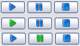
Estados de reproducción.
Reproducir: el pulsado de reproducir pone en marcha la animación creada.(el icono pasa a color verde).
Pausar: congela la imagen en un momento de tiempo y estado concreto.(el icono pasa a color verde).
Parar: paro de la animación.
Duración de la animación:
Tiempo en segundos.
Tiempo en segundos introducido por el usuario como duración de la animación. Este tiempo actualiza la duración en tiempo real cada vez que es modificado.
Modos de reproducción:
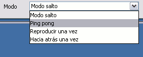
Selector de modos.
Modo salto: la animación llega al final y vuelve a reproducirse desde el principio (salta al principio).
Modo ping pong: la animación llega al final y no salta al principio, se reproduce hacia atrás (efecto ida y vuelta ping pong).
Reproducir una vez (hacia delante): cuando llega al final la animación se detiene.
Hacia atrás una vez: se reproduce desde el último fotograma clave hasta el primero y se detiene.
Relación con la duración: ejemplo si el usuario introduce un tiempo total de 10 segundos.
- Modo salto: inicio a fin = 10 segundos, repetición inicio a fin = 10 segundos… hasta que el usuario detiene la animación.
- Modo ping pong: inicio a fin = 10 segundos, fin a inicio = 10 segundos… hasta que el usuario detiene la animación.
- Reproducir una vez: inicio a fin = 10 segundos; la animación se para automáticamente.
- Hacia atrás una vez: fin a inicio = 10 segundos; la animación se para automáticamente.
NOTA: La frecuencia de refresco del temporizador del reproductor está fijada a 30 frames por segundo.
Animaciones en vistas 2D
Animación de vistas 2D
- Animación de vistas (animación de movimiento)
Consiste en la captura de posiciones del Extent actual de una vista.
La captura de fotogramas clave(posiciones), produce una interpolación de posiciones entre dos fotogramas, con el objetivo de pasar del Extent inicial al Extent final.
- Animación de capas (animación de transparencias)
Consiste en capturar la propiedad de transparencia de capa seleccionada en el TOC.
La transparencia se aplicará una a una a cada capa seleccionada desde su nivel actual de transparencia hasta hacerla desaparecer completamente. Con esto se consigue sensación de cambio temporal en la vista.
Un documento de animación es capaz de animar varias vistas 2D a la vez, tanto animación de vista como de capas por separado aplicando los dos tipos de animación a la vez en una misma vista.
Una vista incluida en un documento de animación no puede ser incluida en otro documento de animación.
Una vista 2D puede ser animada conjuntamente con vistas 3D al mismo tiempo.
NOTA: El método de dibujado en la parte 2D produce un efecto Blinking o parpadeo en la pantalla, que hace que el resultado de las animaciones no sea eficiente por el momento.
Animaciones en vistas 3D
Animación de vistas 3D
- Animación de vistas (animación de movimiento)
Consiste en la captura la posición actual de una vista (posición de la cámara).
La captura de fotogramas clave(posiciones), produce una interpolación de posiciones entre dos fotogramas, con el objetivo de la posición de la cámara inicial a la posición de la cámara final.
- Animación de capas (animación de transparencias)
Consiste en capturar la propiedad de transparencia de capa seleccionada en el TOC.
La transparencia se aplicará una a una a cada capa seleccionada desde su nivel actual de transparencia hasta hacerla desaparecer completamente. Con esto se consigue sensación de cambio temporal en la vista.
Un documento de animación es capaz de animar varias vistas 3D a la vez, tanto animación de vista como de capas por separado aplicando los dos tipos de animación a la vez en una misma vista.
Una vista incluida en un documento de animación no puede ser incluida en otro documento de animación.
Una vista 3D puede ser animada conjuntamente con vistas 2D al mismo tiempo.


